


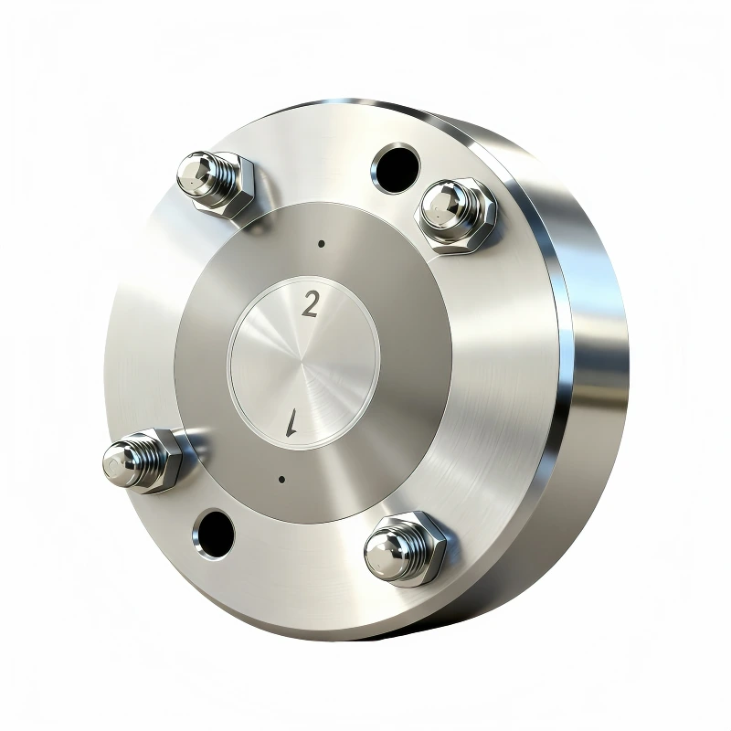
Hollow fiber membrane spinnerets NIPS, 2 Holes
Product advantages
● Extended Service Life
● Robust Needle Design
● Integrated Spinneret Core
● Easy Cleaning and Maintenance
● Convenient Maintenance for MBR Braided Tube Coating Spinneret
● Modular Design with Separate Spinneret Core and Flow Channel Plate
Structural Features
Coaxial dual-channel design: The outer channel delivers the polymer solution (e.g., PES, PAN), while the inner channel injects the bore fluid (e.g., pure water, solvent, or gas), forming a "tube-in-tube" structure. The inner and outer diameters of the spinneret orifices determine the membrane's inner diameter, outer diameter, and wall thickness.
Working Principle
In dry-wet or wet spinning, the polymer solution is extruded from the outer annular gap, while the bore fluid is injected through the central channel. They meet at the spinneret outlet. The polymer solution contacts the external coagulation bath and the internal bore fluid, undergoes phase separation, and solidifies to form a hollow fiber membrane with a skin layer and finger-like or sponge-like pore structure.
Trustech Spinneret Key Design Elements Trustech
These parameters are fundamental to spinneret design and directly determine the membrane's final performance:
|
Parameter |
Description |
Influence on membrane performance |
|
Flow channel (R) |
The runner for transporting, buffering, and distributing the dope and bore fluids. |
Different structures should be optimized according to material properties, viscosity, spinneret orifice size, and hole quantities to achieve optimal spinning performance. |
|
Annular gap width (d) |
The gap (thickness) of the dope flow channel. |
It primarily determines the hollow fiber wall thickness. Narrower gaps yield thinner walls and lower mass-transfer resistance, but may reduce mechanical strength. |
|
Bore tube outer diameter (d₁) |
The outer diameter of the central tube forming the inner wall of the annular gap. |
Together with the outer sleeve inner diameter, it defines the annular gap width. |
|
Outer sleeve inner diameter (d₂) |
The inner diameter of the spinneret outer sleeve forming the outer wall of the annular gap. |
Together with the bore tube outer diameter, it defines the annular gap width and the fiber outer diameter. |
|
Central tube inner diameter (d₃) |
The diameter of the bore fluid channel. |
It primarily determines the fiber inner diameter. The inner diameter affects membrane module packing density and the pressure drop of fluid inside the fiber. |
|
Length-to-gap ratio (L/d) |
The ratio of the flow channel length (L) to the annular gap width (d). |
It affects spinning stability. Designing an appropriate L/d according to material properties and process conditions helps stabilize flow and eliminate entry effects, resulting in more uniform extruded fibers membrane. |
|
Concentricity |
The coaxial alignment among the dope layer inner diameter at the spinneret outlet and the bore tube inner and outer diameters. |
It affects wall-thickness uniformity and bubble point pressure. |
|
Extrusion face geometry |
The foremost geometry of the spinneret, such as flat or micro-tapered. |
It influences draw-down and deformation after extrusion, especially important for the air-gap segment in dry-wet spinning. |
The Advantages of Trustech FCT Spinneret Trustech
The spinneret design covers a wide dope viscosity range, offers strong versatility, high spinning stability, and effectively reduces issues such as filament breaks.
Modular Design with Separate Spinneret Core and Flow Channel Plate: No positioning pins needed, making assembly and disassembly as simple as using a screw.
Integrated Spinneret Core: High precision and good concentricity.
Robust Needle Design: The Bore liquid needle is not easily damaged.
Easy Cleaning and Maintenance: User-friendly cleaning and maintenance ,friendly for non-professional operators
High Reliability: Stable and consistent performance.
Extended Service Life: Longer operational lifespan.
Convenient Maintenance for MBR Braided Tube Coating Spinneret: Spinneret cores can be easily taken out and cleaned without disassembling the flow channel plate.
Product Parameters
|
Brand |
Trustech |
Application |
NIPS |
|
Material |
SUS304, SUS630, SUS316L |
Holes/Pack |
1-32 |
|
Dope inlet Thread |
G1/8, BSP1/8, NPT1/8 |
Minimum membrane OD |
0.20mm |
|
Bore liquid inlet thread |
G1/8, BSP1/8, NPT1/8 |
Customize thread |
Yes |
|
Precision |
±0.002mm |
Concentricity |
0.003mm |
|
Design |
FCT, conventional |
Connections |
Standard |
|
Viscosity application |
1000-300000cp |
Roughness |
Ra0.2-0.8 |
Suitable Materials
PVDF (Polyvinylidene Fluoride), CA (cellulose acetate), PVC (Polyvinyl chloride), PES (Polyethersulfone), PSF/PSU (Polysulfone), PA (Nylon, Polyamide), PAN (polyacrylonitrile)
FCT Design
We can offer FCT designs that allow the spinneret core to be removed, replacing conventional designs where each spinneret hole cannot be independently replaced or disassembled. If one hole has a quality issue, the entire spinneret traditionally needs repair or scrapping. Our FCT spinnerets are independently designed so each hole can be individually replaced if needed. The FCT 6th-generation spinneret enables independent on/off control of the dope feed for each spinneret core, and the 8th-generation FCT spinneret cores can be changed online within a few minute down to 50 seconds when problems occur, to ensure continuous production without downtime.
Common Specifications
|
General Specification |
Application |
Design Type |
Type |
|
0.36/0.28/0.15 |
NIPS |
Independent design |
Single-aperture/ Multi-aperture |
|
0.5/0.28/0.15 |
NIPS |
Independent design |
Single-aperture/ Multi-aperture |
|
0.6/0.4/0.2 |
NIPS |
Independent design |
Single-aperture/ Multi-aperture |
|
0.8/0.4/0.2 |
NIPS |
Conventional design |
Single-aperture/ Multi-aperture |
|
1.3/0.7/0.4 |
NIPS |
Conventional design/ Independent design |
Single-aperture/ Multi-aperture |
|
1.4/0.9/0.6 |
NIPS |
Conventional design/ Independent design |
Single-aperture/ Multi-aperture |
|
1.5/0.9/0.6 |
NIPS |
Conventional design/ Independent design |
Single-aperture/ Multi-aperture |
|
1.6/0.7/0.4 |
NIPS |
Conventional design/ Independent design |
Single-aperture/ Multi-aperture |
|
1.8/0.9/0.5 |
NIPS |
Conventional design/ Independent design |
Single-aperture/ Multi-aperture |
|
1.8/1.2/0.6 |
NIPS |
Conventional design/ Independent design |
Single-aperture/ Multi-aperture |
|
2.0/1.0/0.7 |
NIPS |
Conventional design/ Independent design |
Single-aperture/ Multi-aperture |
|
3.1/1.8/1.5 |
NIPS |
Conventional design/ Independent design |
Single-aperture/ Multi-aperture |
Customer Membrane Examples
ACHIEVEMENTS
FAQ
About Trustech