


Hollow Fiber Membrane Spinneret FCT Generation 6th, Braided Tube Reinforced Spinning
Product Overview
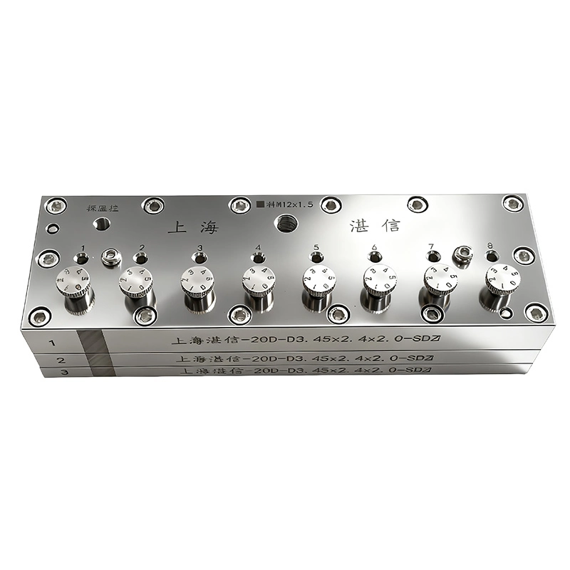
FCT generation 6th hollow fiber membrane spinneret not only has the functions of independent installment and replacement, but also features independent control of the dope solution despite the pressure and fluctuation. Take the 8-nozzle products as an example, if one spinneret core is closed by the control valve, the flow rate of other spinnerets holes will be adjusted at the same time.
During the spinning process, taking the FCT 6th generation 8 holes braided tube hollow spinneret as an example, if a membrane filament from one of the holes becomes blocked or shows quality issues, that single hole can be shut off without affecting the normal spinning of the other seven holes. Spinning can continue until the end of the entire shift or until the reactor batch is fully processed, after which cleaning and maintenance can be performed significantly improving efficiency. Customers commonly use 4 holes and 8 holes FCT spinnerets.
Structural Features
The module design of flow rate control of FCT generation 6th hollow fiber spinneret is simple in structure and easy to operate, each spinneret hole can be individually controlled.
Trustech Spinneret Key Design Elements Trustech
These parameters are fundamental to spinneret design and directly determine the membrane's final performance:
|
Parameter |
Description |
Influence on membrane performance |
| Flow channel (R) | The runner for transporting, buffering, and distributing the dope and bore fluids. | Different structures should be optimized according to material properties, viscosity, spinneret orifice size, and hole quantities to achieve optimal spinning performance. |
| Annular gap width (d) | The gap (thickness) of the dope flow channel. | It primarily determines the hollow fiber wall thickness. Narrower gaps yield thinner walls and lower mass-transfer resistance, but may reduce mechanical strength. |
| Bore tube outer diameter (d₁) | The outer diameter of the central tube forming the inner wall of the annular gap. | Together with the outer sleeve inner diameter, it defines the annular gap width. |
| Outer sleeve inner diameter (d₂) | The inner diameter of the spinneret outer sleeve forming the outer wall of the annular gap. | Together with the bore tube outer diameter, it defines the annular gap width and the fiber outer diameter. |
| Central tube inner diameter (d₃) | The diameter of the bore fluid channel. | It primarily determines the fiber inner diameter. The inner diameter affects membrane module packing density and the pressure drop of fluid inside the fiber. |
| Length-to-gap ratio (L/d) | The ratio of the flow channel length (L) to the annular gap width (d). | It affects spinning stability. Designing an appropriate L/d according to material properties and process conditions helps stabilize flow and eliminate entry effects, resulting in more uniform extruded fibers membrane. |
| Concentricity | The coaxial alignment among the dope layer inner diameter at the spinneret outlet and the bore tube inner and outer diameters. | It affects wall-thickness uniformity and bubble point pressure. |
| Extrusion face geometry | The foremost geometry of the spinneret, such as flat or micro-tapered. | It influences draw-down and deformation after extrusion, especially important for the air-gap segment in dry-wet spinning. |
The Advantages of Trustech FCT Gneration 6th Spinneret Trustech
The spinneret design covers a wide dope viscosity range, offers strong versatility, high spinning stability, and effectively reduces issues such as filament breaks.
Independent on/off control per orifice for non-stop production:
Each spinneret core (orifice) has its own dope on/off valve and flow control. If one orifice is blocked or a filament breaks, that single orifice can be shut off without stopping the entire line, significantly improving production continuity and efficiency.
Auto flow self-adjustment:
When one orifice is closed, the remaining seven automatically adjust their flow and continue normal spinning. Spinneret can self-adapt under certain pressure fluctuations to maintain consistent multi-orifice quality, significantly reducing the impact of filament breaks and blockages.
Efficient, convenient maintenance:
The spinneret plate and cores can be cleaned and serviced without disassembling the flow channel plate.
Wide viscosity window:
The FCT design supports production from low viscosity at 2,000 cP up to high viscosity at 300,000 cP, and is compatible with mainstream polymers such as PVDF, PES, PSf, and PAN.
Product Parameters
| Brand | Trustech | Application | Braided tube |
| Material | SUS304, SUS630, SUS316L | Holes/Pack | 8 |
| Dope inlet Thread | G1/8, BSP1/8, NPT1/8 | Minimum membrane OD | 1.0mm |
| Bore liquid inlet thread | G1/8, BSP1/8, NPT1/8 | Customize thread | Yes |
| Precision | ±0.002mm | Concentricity | 0.003mm |
| Design | FCT design | Connections | Standard |
| Viscosity application | 1000-300000cp | Roughness | Ra0.2-0.8 |
| Solvent | DMAC, DMF, NMP | Temperature | 150℃ |
Suitable Materials
PVDF (Polyvinylidene Fluoride), CA (cellulose acetate), PVC (Polyvinyl chloride), PES (Polyethersulfone), PSF/PSU (Polysulfone), PA (Nylon, Polyamide), PAN (polyacrylonitrile)
FCT Design
We can offer FCT designs that allow the spinneret core to be removed, replacing conventional designs where each spinneret hole cannot be independently replaced or disassembled. If one hole has a quality issue, the entire spinneret traditionally needs repair or scrapping. Our FCT spinnerets are independently designed so each hole can be individually replaced if needed. The FCT 6th-generation spinneret enables independent on/off control of the dope feed for each spinneret core, and the 8th-generation FCT spinneret cores can be changed online within a few minute down to 50 seconds when problems occur,to ensure continuous production without downtime.
Common Specifications
| No. | General Specification | Application | Design Type | Type |
| 1 | 2.3/1.5/1.0 | Braided tube | FCT design | Single-aperture/ Multi-aperture |
| 2 | 2.3/1.5/1.2 | Braided tube | FCT design | Single-aperture/ Multi-aperture |
| 3 | 2.7/1.5/1.2 | Braided tube | FCT design | Single-aperture/ Multi-aperture |
| 4 | 2.2/1.7/1.4 | Braided tube | FCT design | Single-aperture/ Multi-aperture |
| 5 | 2.7/2.2/1.9 | Braided tube | FCT design | Single-aperture/ Multi-aperture |
| 6 | 2.8/2.0/1.5 | Braided tube | FCT design | Single-aperture/ Multi-aperture |
| 7 | 2.8/2.2/1.9 | Braided tube | FCT design | Single-aperture/ Multi-aperture |
| 8 | 2.8/2.3/2.0 | Braided tube | FCT design | Single-aperture/ Multi-aperture |
| 9 | 2.9/1.4/1.1 | Braided tube | FCT design | Single-aperture/ Multi-aperture |
| 10 | 2.9/1.8/1.5 | Braided tube | FCT design | Single-aperture/ Multi-aperture |
| 11 | 2.9/1.9/1.6 | Braided tube | FCT design | Single-aperture/ Multi-aperture |
| 12 | 3.0/2.3/1.9 | Braided tube | FCT design | Single-aperture/ Multi-aperture |
| 13 | 3.0/2.3/2.0 | Braided tube | FCT design | Single-aperture/ Multi-aperture |
| 14 | 3.1/2.8/2.5 | Braided tube | FCT design | Single-aperture/ Multi-aperture |
| 15 | 3.2/2.2/1.8 | Braided tube | FCT design | Single-aperture/ Multi-aperture |
| 16 | 3.4/1.7/1.4 | Braided tube | FCT design | Single-aperture/ Multi-aperture |
| 17 | 3.4/2.2/1.8 | Braided tube | FCT design | Single-aperture/ Multi-aperture |
| 18 | 3.7/1.9/1.6 | Braided tube | FCT design | Single-aperture/ Multi-aperture |
| 19 | 3.8/2.2/1.9 | Braided tube | FCT design | Single-aperture/ Multi-aperture |
| 20 | 3.8/2.3/2.0 | Braided tube | FCT design | Single-aperture/ Multi-aperture |
| 21 | 3.8/2.3/2.0 | Braided tube | FCT design | Single-aperture/ Multi-aperture |
| 22 | 4.0/2.5/2.1 | Braided tube | FCT design | Single-aperture/ Multi-aperture |
| 23 | 4.0/3.0/2.5 | Braided tube | FCT design | Single-aperture/ Multi-aperture |
Customer Membrane Examples
ACHIEVEMENTS
FAQ
About Trustech