


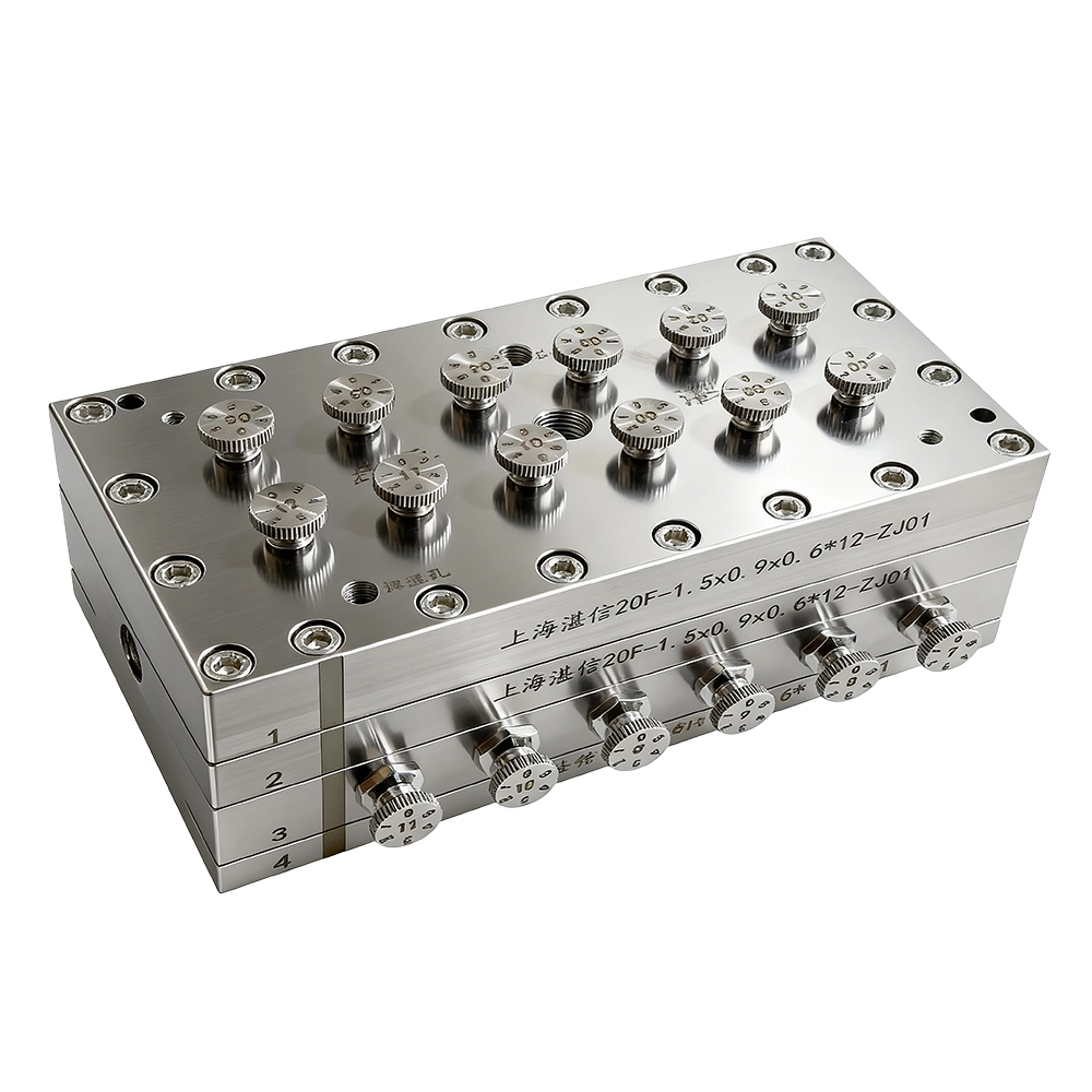
FCT NIPS 6th generation hollow fiber spinneret 12 holes, on-off control function
Core working principle
Parallel multiple holes layout with independent supply:
Inside the hollow fiber spinneret plate, the bore fluid and dope are split into multiple parallel, independent branches. Each spinneret hole is equipped with its own valve set, microflow control and sealing module, achieving dual independent start and stop for "bore fluid + dope" on a per holes basis.
Fast Control:
When a given spinneret hole exhibits spinning quality abnormalities (e.g., filament breakage, eccentricity, clogging, or ratio fluctuations), the bore fluid and dope of that hole can be shut off immediately to isolate the faulty hole; the remaining holes continue stable spinning, keeping the line running and capacity unaffected.
Scalable multiple holes architecture:
Through modular distribution and isobaric flow channel design, FCT 6th generation hollow fiber spinneret even when scaling to 8/12/16 holes, each hole still receives stable, repeatable flow and shear conditions.
Core features of the FCT 6th generation spinneret plate
Multiple holes expansion capability: breaking capacity bottlenecks and enabling scale-up
Per holes independent control: precise loss mitigation and true "non-stop production"
Continued and upgraded FCT advantages: precision meets easy maintenance
Strong scenario adaptability: targeting process pain points to empower industrial upgrades
Trustech Spinneret Key Design Elements Trustech
These parameters are fundamental to spinneret design and directly determine the membrane's final performance:
|
Parameter |
Description |
Influence on membrane performance |
| Flow channel (R) | The runner for transporting, buffering, and distributing the dope and bore fluids. | Different structures should be optimized according to material properties, viscosity, spinneret orifice size, and hole quantities to achieve optimal spinning performance. |
| Annular gap width (d) | The gap (thickness) of the dope flow channel. | It primarily determines the hollow fiber wall thickness. Narrower gaps yield thinner walls and lower mass-transfer resistance, but may reduce mechanical strength. |
| Bore tube outer diameter (d₁) | The outer diameter of the central tube forming the inner wall of the annular gap. | Together with the outer sleeve inner diameter, it defines the annular gap width. |
| Outer sleeve inner diameter (d₂) | The inner diameter of the spinneret outer sleeve forming the outer wall of the annular gap. | Together with the bore tube outer diameter, it defines the annular gap width and the fiber outer diameter. |
| Central tube inner diameter (d₃) | The diameter of the bore fluid channel. | It primarily determines the fiber inner diameter. The inner diameter affects membrane module packing density and the pressure drop of fluid inside the fiber. |
| Length-to-gap ratio (L/d) | The ratio of the flow channel length (L) to the annular gap width (d). | It affects spinning stability. Designing an appropriate L/d according to material properties and process conditions helps stabilize flow and eliminate entry effects, resulting in more uniform extruded fibers membrane. |
| Concentricity | The coaxial alignment among the dope layer inner diameter at the spinneret outlet and the bore tube inner and outer diameters. | It affects wall-thickness uniformity and bubble point pressure. |
| Extrusion face geometry | The foremost geometry of the spinneret, such as flat or micro-tapered. | It influences draw-down and deformation after extrusion, especially important for the air-gap segment in dry-wet spinning. |
The Advantages of Trustech FCT 6th Generation Spinneret Trustech
The spinneret design covers a wide dope viscosity range, offers strong versatility, high spinning stability, and effectively reduces issues such as filament breaks.
Extending FCT's fast change, high precision advantages to complex conditions and large scale manufacturing
Inheriting the 5th generation pinless structure with 0.002 mm machining precision, eliminating the need for concentricity adjustment. It is particularly suitable for R&D or mass production scenarios with unstable materials (e.g., PVDF, polyamide) and large process fluctuations, significantly reducing scrap rate, shortening R&D cycles, and enabling large scale precision manufacturing of high end membranes for water treatment, MBR, hemodialysis, and more.
Precise per-orifice independent control
Each spinneret orifice is equipped with independent control units for the bore fluid and casting dope, allowing material feed to a faulty orifice to be cut off individually. This prevents whole-line stoppage due to a single-orifice failure and, under unstable materials or fluctuating processes, reduces raw material waste by over 30%, lowers defect rates, and improves production continuity.
Product Parameters
| Brand | Trustech | Application | NIPS |
| Material | SUS304, SUS630, SUS316L | Holes/Pack | 8-12 |
| Dope inlet Thread | G1/8, BSP1/8,NPT1/8 | Minimum membrane OD | 0.20mm |
| Bore liquid inlet thread | G1/8, BSP1/8,NPT1/8 | Customize thread | Yes |
| Precision | ±0.002mm | Concentricity | 0.003mm |
| Design | FCT, conventional | Connections | Standard |
| Viscosity application | 1000-300000cp | Roughness | Ra0.2-0.8 |
| Solvent | DMAC, DMF, NMP | Temperature | 150℃ |
Suitable Materials
PVDF (Polyvinylidene Fluoride), CA (cellulose acetate), PVC (Polyvinyl chloride), PES (Polyethersulfone), PSF/PSU (Polysulfone), PA (Nylon, Polyamide), PAN (polyacrylonitrile)
FCT Design
We can offer FCT designs that allow the spinneret core to be removed, replacing conventional designs where each spinneret hole cannot be independently replaced or disassembled. If one hole has a quality issue, the entire spinneret traditionally needs repair or scrapping. Our FCT spinnerets are independently designed so each hole can be individually replaced if needed. The FCT 6th-generation spinneret enables independent on/off control of the dope feed for each spinneret core, and the 8th-generation FCT spinneret cores can be changed online within a few minute down to 50 seconds when problems occur, to ensure continuous production without downtime.
Common Specifications
| No. | General Specification | Application | Design Type | Type |
| 1 | 0.35/0.19/0.13 | NIPS | FCT design | Single-aperture/ Multi-aperture |
| 2 | 0.40/0.19/0.13 | NIPS | FCT design | Single-aperture/ Multi-aperture |
| 3 | 0.5/0.28/0.15 | NIPS | FCT design | Single-aperture/ Multi-aperture |
| 4 | 0.6/0.4/0.2 | NIPS | FCT design | Single-aperture/ Multi-aperture |
| 5 | 0.8/0.4/0.2 | NIPS | FCT design | Single-aperture/ Multi-aperture |
| 6 | 1.3/0.7/0.4 | NIPS | FCT design | Single-aperture/ Multi-aperture |
| 7 | 1.4/0.8/0.6 | NIPS | FCT design | Single-aperture/ Multi-aperture |
| 8 | 1.5/0.9/0.6 | NIPS | FCT design | Single-aperture/ Multi-aperture |
| 9 | 1.6/1.0/0.6 | NIPS | FCT design | Single-aperture/ Multi-aperture |
| 10 | 1.8/1.1/0.5 | NIPS | FCT design | Single-aperture/ Multi-aperture |
| 11 | 1.9/1.2/0.6 | NIPS | FCT design | Single-aperture/ Multi-aperture |
| 12 | 2.0/1.0/0.7 | NIPS | FCT design | Single-aperture/ Multi-aperture |
| 13 | 3.1/1.8/1.5 | NIPS | FCT design | Single-aperture/ Multi-aperture |
| 14 | 3.1/1.8/1.5 | NIPS | FCT design | Single-aperture/ Multi-aperture |
| 15 | 3.2/2.2/1.8 | NIPS | FCT design | Single-aperture/ Multi-aperture |
| 16 | 3.3/1.1/0.9 | NIPS | FCT design | Single-aperture/ Multi-aperture |
| 17 | 3.4/2.4/2.0 | NIPS | FCT design | Single-aperture/ Multi-aperture |
Customer Membrane Examples
ACHIEVEMENTS
FAQ
About Trustech